Under the Bonnet: Hardware


Part 1 covered the what and the why. This is part two of three - and this one is all hardware. Part three will be the software equivalent: the Dart backend, Docker setup, and Flutter app.
Here we go under the bonnet of the physical stack - the RFID reader, the industrial camera, the network they sit on, and how data moves from the track into the backend.
The Data Flow
To recap from part 1, every component communicates through the Dart backend - nothing talks directly to anything else. Here's how a single lap flows end-to-end:
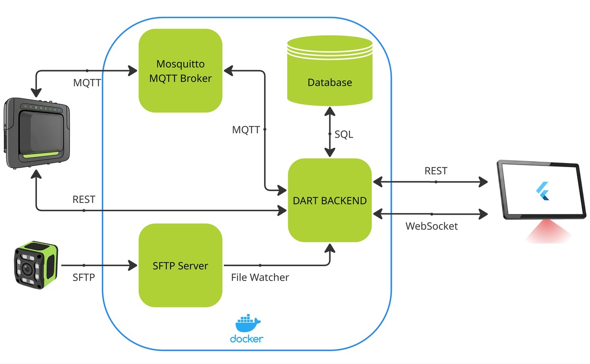
- The player logs into the game, triggering a REST call to the backend.
- The backend configures the RFID reader.
Game begins - car goes around the track and crosses the start/finish line.
- The RFID reader detects the tag and publishes the car ID and timestamp over MQTT to the Mosquitto broker, which forwards it to the backend.
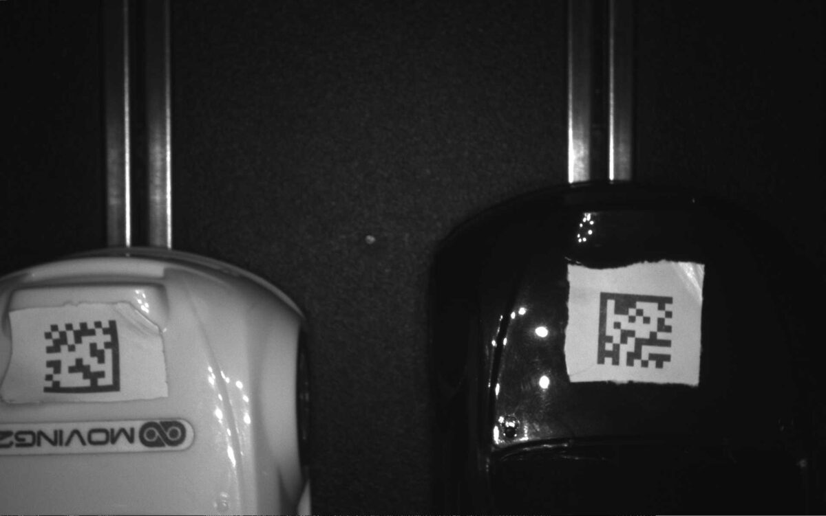
- Simultaneously, the car breaks the light beam. The camera scans for the QR code, and when spotted, saves the image over SFTP to a directory watched by the backend.
- The backend validates the lap and broadcasts the result to the Flutter frontend over WebSocket.
- Once the game is complete, lap times are written to the PostgreSQL database.
The key design principle here is that the backend is the single source of truth. The Flutter app never talks to the RFID reader directly. The camera never talks to the app. Everything goes through one place - which made debugging and testing significantly easier.
Networking
All devices sit on a local LAN with no internet access. Much like how we used some old laptop, we also used some old router. Each device is connected over ethernet using the router's LAN ports, and assigned a static IP - the RFID reader, the camera, the laptop running the backend, and the kiosk.
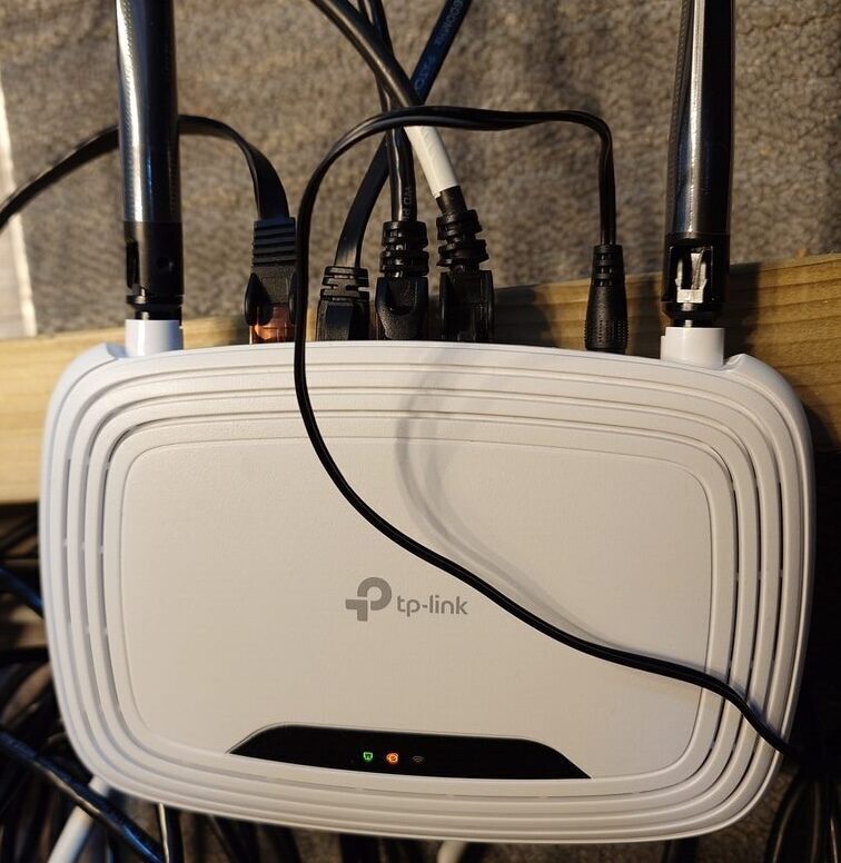
Static IPs matter here because every device is addressed by IP in config files and Docker environment variables. If addresses shifted between sessions, nothing would connect. They also let us reach the web UIs on the Zebra devices directly from a laptop on the same network, which made initial setup straightforward - just type the IP into a browser for basic setup.
RFID
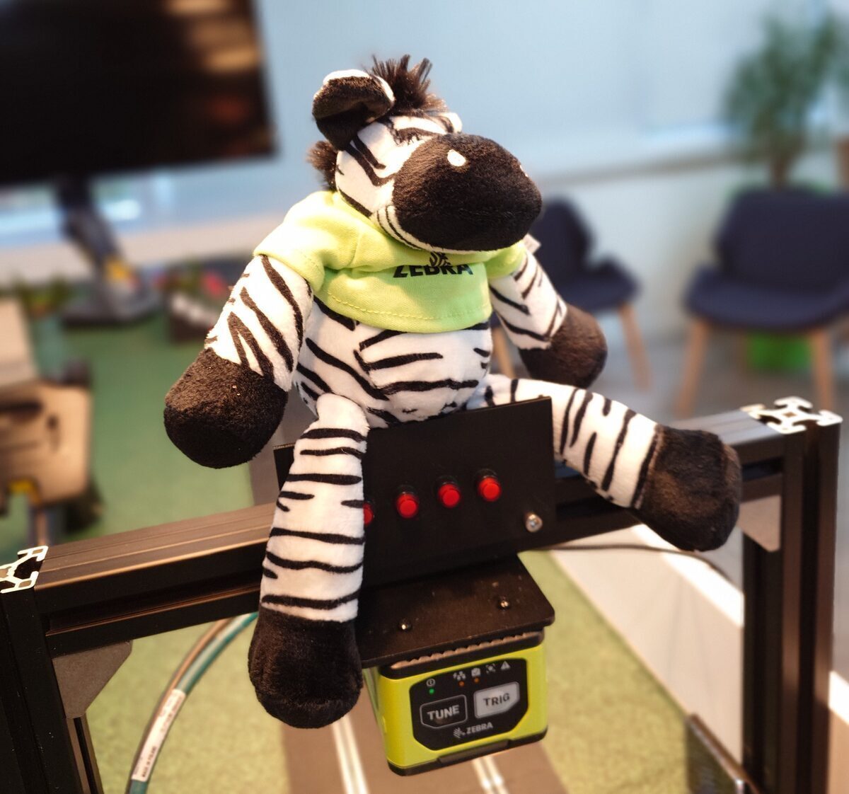
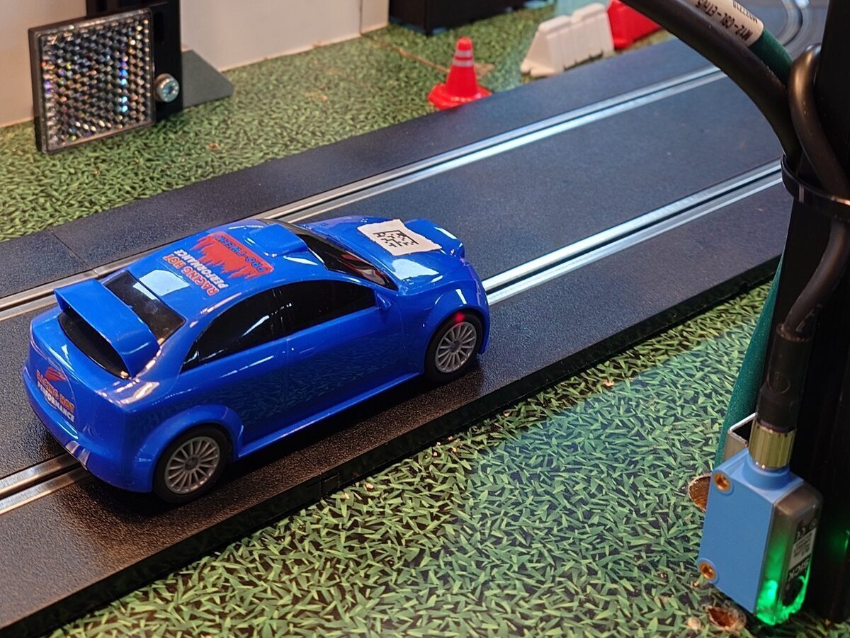
Each car carries a passive RFID tag hidden under the bonnet. When it passes beneath the antenna mounted in the bridge at the start/finish line, the antenna powers the tag inductively and reads its ID in an instant. That read - car ID plus timestamp - is what powers the entire lap timing system.
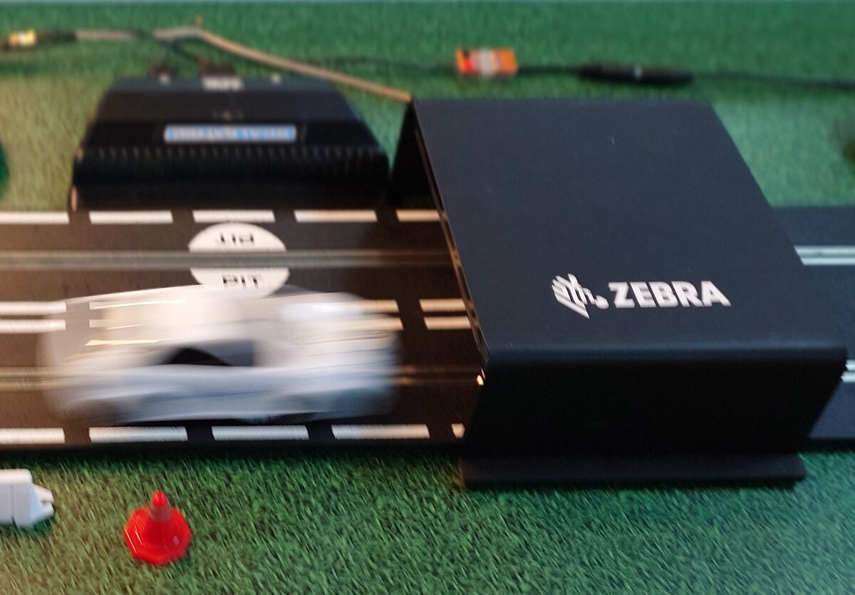
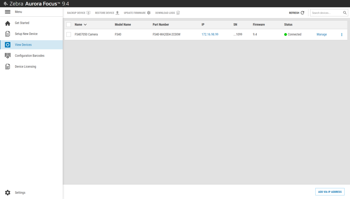
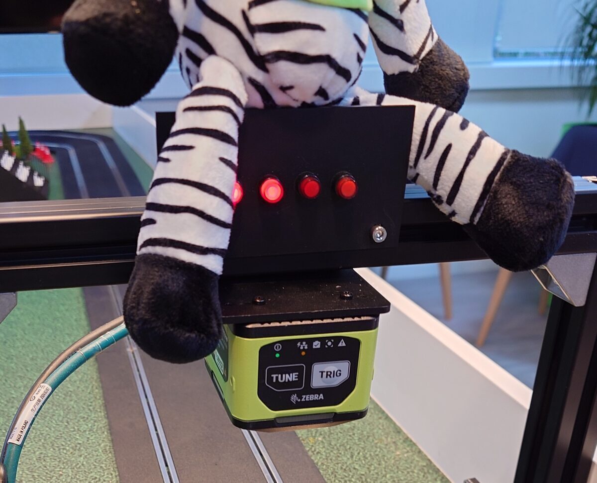
All of this data comes from our Zebra FX7500 RFID reader, configured through its built-in web UI. The first step is setting a static IP.
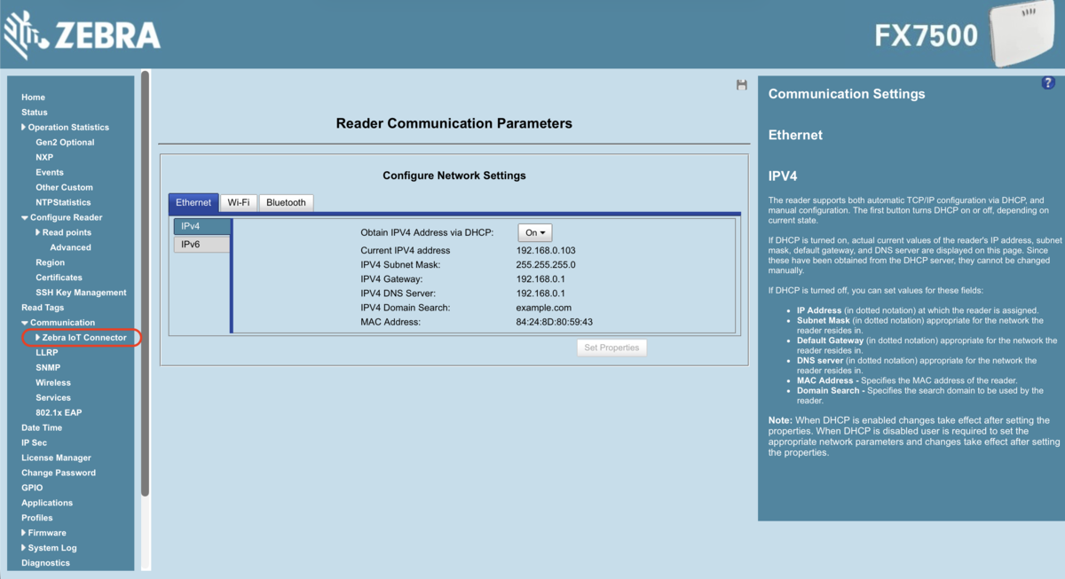
IoT Connector
All the settings we need are under Read Tags > Communication > Zebra IoT Connector. There are three things to configure here: Configuration, Operating Mode, and Connection.
Configuration
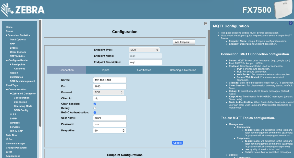
The Configuration page defines how the RFID reader publishes its data. There are a range of options - cloud buckets, REST APIs, WebSockets, USB. We initially tried our own REST API, but the latency was too high and the UI couldn't keep up with the pace of reads. Switching to MQTT gave us a significant speed improvement, and it's what we'd recommend from the start.
To set this up, create a new configuration and set the endpoint type to MQTT. Fill in the broker details - address, port (1883), and credentials to authenticate the connection.
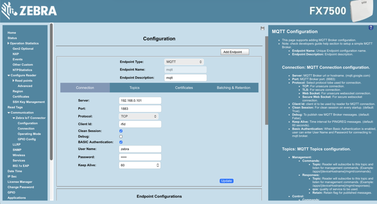
The Topics tab is where you configure the MQTT topics used for tag reads and reader control. We set up the following:
| Topic | Direction | Purpose |
|---|---|---|
/rfid | Reader → Broker | Tag read events |
/rfid/control | Backend → Reader | Enable / disable scanning |
/rfid/control-resp | Reader → Backend | Acknowledge control message |
/rfid/management | Backend → Reader | Configure reader |
/rfid/management-resp | Reader → Backend | Acknowledge management message |
At game start, the backend sends the operating mode config as a JSON payload to /rfid/management. Once the reader acknowledges on /rfid/management-resp, play begins. The backend also controls the reader's active state - enabling it at game start and disabling it at the end, cutting down on noise between sessions and ensuring reads are only processed when a game is actually running.
Operating Mode
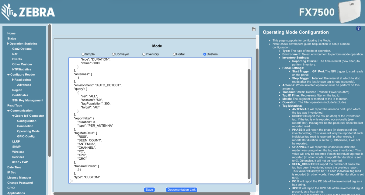
The operating mode defines how the physical RFID tags are read - when the antennas are active, for how long, and what pattern of reads are reported. This is configured within the IoT Connector's Operating Mode page.
Shockingly, the FX7500 doesn't ship with a built-in mode designed for tracking small plastic cars at racing speed every few seconds. So we created a custom one.
{
  "type": "CUSTOM",
  "antennaStopCondition": { "type": "DURATION", "value": 100 },
  "transmitPower": [21],
  "antennas": [1],
  "query": [{ "sel": "ALL", "session": "S0", "target": "AB" }],
  "reportFilter": { "duration": 0, "type": "PER_ANTENNA" }
}
- Antenna Stop Condition - in CUSTOM mode, the reader has no default sweep behaviour, so we set a 100ms duration per antenna cycle. Without this, the reader doesn't know when to stop each sweep and restart - you need to give it a bound.
- Transmit Power - lowering the power narrows the effective read zone. At 21 dBm, we got reliable reads at the finish line without picking up tags elsewhere on the track. Your mileage will vary depending on antenna placement and environment.
- Session Mode - S0 reports all tag reads whenever a tag is present. This means the reader fires frequently, but we wanted all the raw data landing on the backend where we could validate it properly - filtering duplicates and near-misses in software rather than trusting the reader to do it.
For more information on RFID operating modes, see the docs.
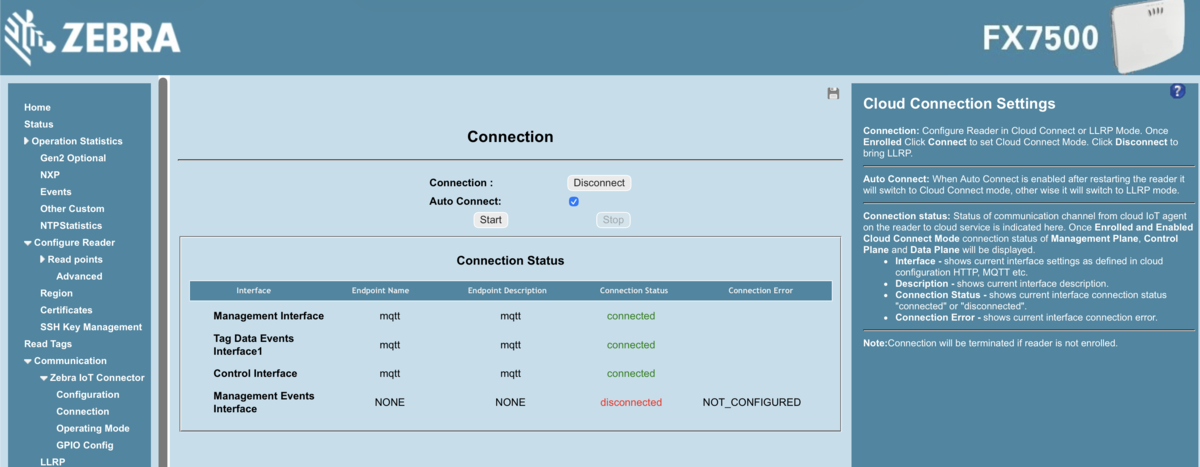
Connection
Once the operating mode and configuration are set, the reader is ready to go. All confirmed endpoints are listed in the Connection page table. Hit Connect and the reader starts scanning immediately, with the IoT Connector status panel confirming the live MQTT broker connection.
One thing worth noting: there is an Auto-start checkbox. This turns on communication at boot, which is essential for a production deployment - but during development it can get in the way. We left it off and connected manually each session.
From here, tag reads are flowing over MQTT to the backend. Part 3 covers what happens next.
For more information on IoT Connector, see the docs.
Machine Vision
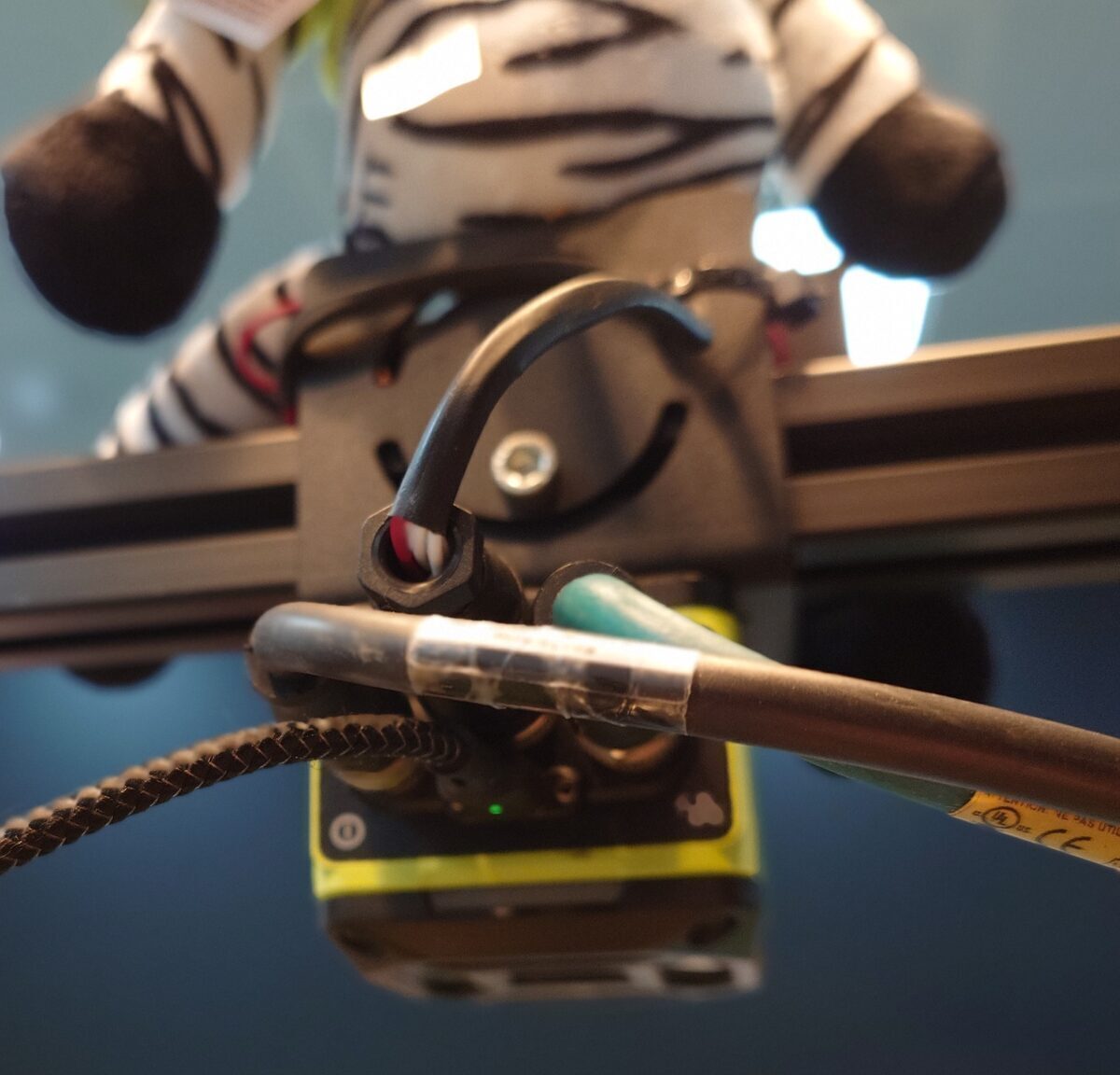
The machine vision side handles capturing images of the cars as they cross the finish line. The FS40 sits in a gantry directly above the track, paired with a light beam that acts as its trigger.
At a high level, the camera needs to:
- Watch for the light beam to break
- Attempt to read the QR code on the car within a 200ms window
- Activate the correct lights on the gantry based on which car triggered it
- Save and send the image via SFTP to the backend
We configured the FS40 using Aurora, Zebra's dedicated camera configuration software. Aurora lets you create jobs that load directly onto the hardware and run continuously - exactly what we needed, since the job doesn't change between sessions.
Aurora Focus
Connect the camera to your laptop to get started. One important prerequisite: your camera firmware version and Aurora version need to match. If they don't, you'll need to update one or the other before the device appears.
Once that's sorted, you'll see the device in Aurora, ready to configure:
Capture
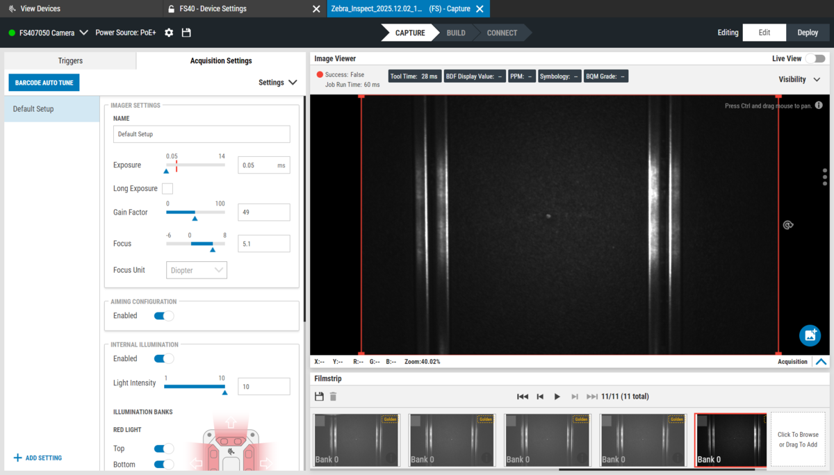
Clicking Manage takes you into the real configuration, starting with Capture. This is where you set your triggers and acquisition settings.
For Triggers, we used GPIO - this is the physical connection between the light beam gantry and the back of the camera. When the beam breaks, the GPIO signal fires and the camera captures:
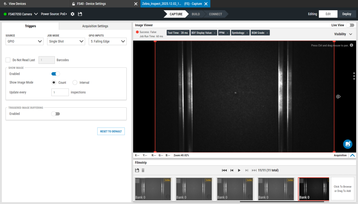
In Acquisition Settings, you can tune Exposure, Gain, Focus, and anything else that affects image quality. The goal is a consistently clean, readable frame - not a beautiful photo. Tune these for the lighting conditions in your specific environment:
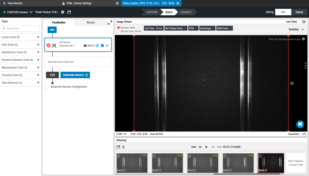
Build
With capture configured, Build is where you define what the camera actually does when it triggers - in our case, read a QR code. Our setup is a single job, which is about as simple as Aurora gets. That said, these devices support multiple parallel jobs and are capable of significantly more complex logic. The left-hand panel gives a good sense of what's available out of the box:
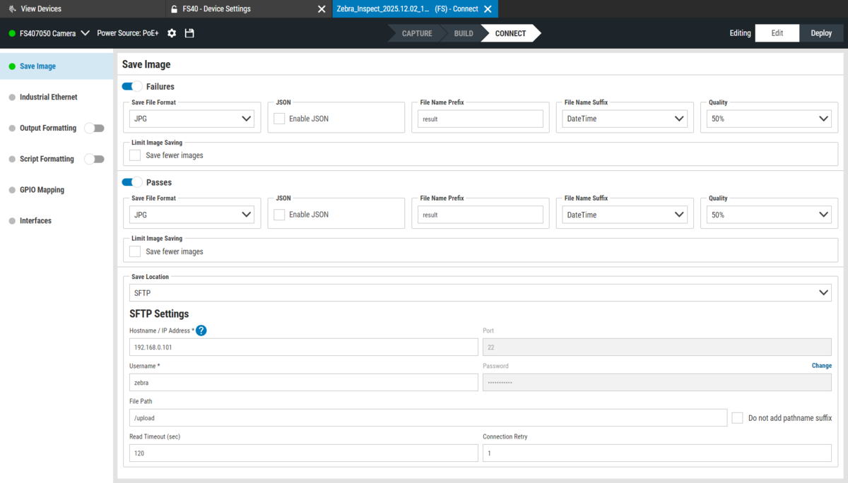
Connect
Connect is the output tab. This is where you configure image format, metadata, and where everything gets sent.
We kept it straightforward - JPG images only, no JSON sidecar files. One important decision: we configured the camera to save both successful and unsuccessful QR code scans. If the QR wasn't read, we still capture and display the image. A blurry finish line photo with no car ID is more useful than nothing - at least the player knows the lap was registered.
Images are sent over SFTP to the backend server. The File Path setting determines the folder images are saved into. We used this to make cleanup easy: the frontend deletes the entire folder after each race, and the camera recreates it automatically on the next capture. No image accumulation, no manual cleanup between sessions:
GPIO Mapping is also configured here. The GPIO input from the light beam triggers the scan.
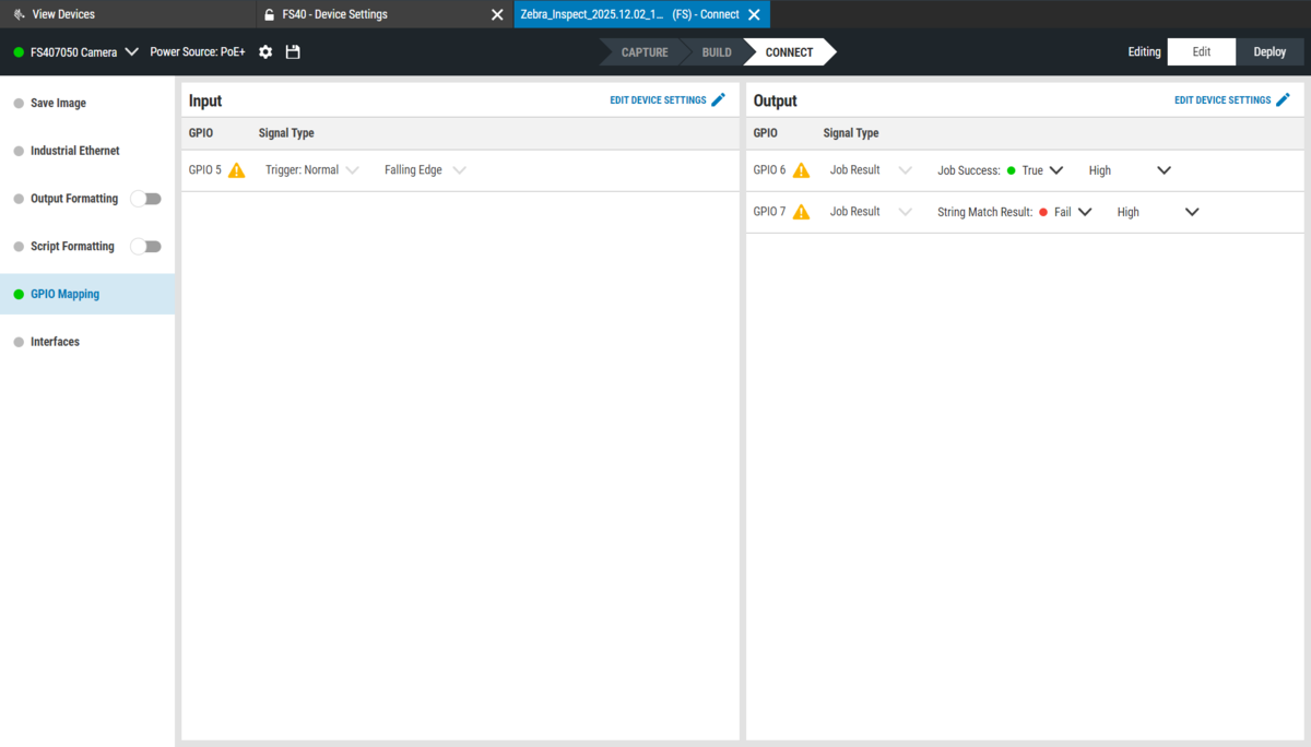
The GPIO output lights up the corresponding side of the gantry once the QR code is successfully read. One cable doing double duty - trigger in, lights out.
Light Beam
The light beam is what makes the trigger consistent. When a car breaks the beam, a signal fires to the camera, which captures the image 200ms later. That window gives the car enough time to get fully into frame, so the QR code is centred and readable regardless of speed.
The Result
The backend receives an image moments after the car crosses the line. Considering the speed, they're surprisingly sharp - sharp enough to clearly show the car mid-crossing. Each one appears live on the kiosk and TV the moment it arrives.
For more information on Aurora, see the docs.
Lessons Learnt
Start with MQTT. We initially tried a REST API for the RFID reader and had to migrate to MQTT once it was clear the latency wasn't acceptable. MQTT is the right choice for this kind of high-frequency event stream - we should have reached for it first.
Light beam sensitivity. The GPIO trigger worked well at racing speeds, but at low throttle a slow-moving car could drift through the beam in a way that confused the 200ms capture window. Adjusting the trigger delay and window duration would help, and it's worth testing across a range of speeds rather than just flat out.
RFID power tuning. 21 dBm worked for our setup, but landing on that number took real trial and error. The right value depends heavily on antenna placement, the tags you're using, and the environment. A more systematic approach - stepping through power levels against a range of speeds and positions - would save time and give more confidence in edge cases.
Why Enterprise Hardware?
It's worth noting that for this project we used enterprise-grade hardware. That said, you could build something very similar with much cheaper alternatives - and if you already have a laptop and a webcam, potentially for nothing at all.
The cars in our setup carry both an RFID tag and a QR code. The RFID reader handles identification; the FS40 reads the QR code and captures the photo. A webcam running OpenCV at the finish line could do both jobs at once - detect the car crossing using frame differencing, read the QR code to identify which car it is, and save the image, all in a single pipeline. You'd be trading precision for cost, and QR code reads become less reliable the faster the car moves. But for a casual setup, it would work.
You could also go further than we did - pressure sensors under the track surface, additional timing gates, a bird's-eye-view camera tracking individual track sectors, more RFID antennas to get precise location, gyroscopes to track car crashes. The backend doesn't care what the source is, as long as it can send an event. This project is very much a starting point; the sky's the limit.
Part 3 will cover the software - the Dart backend, Docker setup, Flutter app, and what we'd change on the code side - when we get around to writing it!
Resources
- The project on GitHub: thelukewalton/scalextric-game
- Zebra Developer Docs: developer.zebra.com
- Zebra Open Source: github.com/zebradevs